The Pocket Guide to Excellent V-Scoring
FAQ # 4 -- How Wide?
Actually, almost no one asks this question... but they should. Understanding the variables that determine score width along with the associated process tolerances, will help you identify problematic specifications, and aid greatly in laying out a manufacturable product. Knowing what your score width will be is essential to design and planning. Understanding the variables that determine score line width is, once again, quite straightforward.
Variables
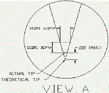
Score line width is determined by a combination of two elements; blade angle and blade wear. Simply stated, a blade of a larger angle will cut a wider path than a blade of a narrower angle, at the same depth. Also, the deeper the blade penetrates the surface of the board, the wider the path will be. Also, as the blade wears, the tip essentially "moves up" the width of the blade, resulting in a wider score path for the same given web. Note View A...
As you can see, there is a little more to score width than meets the eye. For the sake of simplicity and real world conditions, we can be safe in saying that, a 30 degree blade, throughout its service life, will require a surface clearance of .020" +/-.004". To this number we can add equipment tolerances at +/-.002" and you fill in the next number -- which is your accumulated process tolerances, including drill and image registration, as well as material movement. Just to be safe, lets say that it is +/-.004". So, have you done the math yet? At the outside range, we can safely design and plan for a blade clearance, or "Keep Out" area, of approximately .030". Another way to look at it is that the score path is going to encroach into the top and bottom surfaces of the individual boards approximately .015" from the edge (center of the score line) into both images. So far so good? Now lets take a look at a specific project. What is the distance from the nearest surface feature to the board edge? We now know that from the center of the score line (the board edge) to the outside of the path requires approximately .015". For planning purposes then, this becomes your minimum clearance from each board edge. If the board design has this clearance, or more, from the nearest feature to the edge, then you can safely step the board correctly at "zero spacing". Remember, if you add a space between boards, you will effectively be increasing the board size! This mistake will then require that you make two closely spaced score lines between each board to attain the correct board size (not fun to de-panel). But, if you do not have this minimum clearance, there is a good chance that the boards may have to be scrapped all together.
The following illustrates this most critical concept...
Assuming .062" Panel and 30 Degree Score Angle


